

A 2512 resistor’s power rating doesn’t tell you how hot it will run on your PCB. The actual temperature depends on the heat path around it, which is why 2512 current sense resistor heat dissipation on multi-layer boards can differ from what a datasheet rating alone suggests. Copper area, connected planes, vias, and the board’s operating environment all influence how effectively heat moves away from the component.
Start with the rated power, but don’t treat it as a complete thermal estimate for a dense, real-world layout. Calculate dissipation from operating current and resistance, then assess the board’s ability to spread heat. Temperature also matters to measurement: resistance drift can affect current-sense accuracy, depending on the resistor’s temperature coefficient.
This article explains how multilayer stackup, copper geometry, pad design, and thermal vias affect a 2512 resistor’s operating temperature. You’ll learn how to estimate I²R losses, interpret datasheet derating guidance without treating test-board results as your own, and validate performance under realistic operating conditions. This gives you a practical basis for balancing thermal margin with reliable current measurement.
Key Takeaways
- Estimate resistor dissipation using worst-case current and resistance, then assess temperature against the applicable datasheet guidance and board conditions.
- Trace the thermal path from the resistor through its terminations and solder joints into PCB copper to understand why similar components can run at different temperatures.
- Compare compact copper with broader, layer-connected layouts to weigh potential heat-spreading benefits against the space they require.
- Evaluate 2512 current sense resistor heat dissipation on multi-layer boards under realistic steady-state and pulsed operating conditions.
- Carry resistance, current, footprint, and thermal requirements into component selection. Specification sheets and samples can support pin-for-pin replacement evaluation.
Why a 2512 Current Sense Resistor Runs Hot on a Multilayer Board
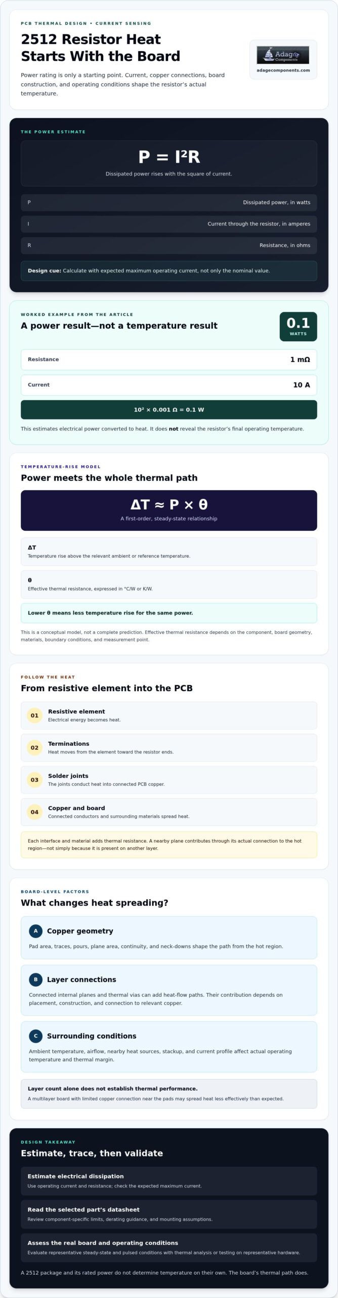
A resistor heats because it converts electrical energy into heat. For a current-sense resistor, the basic estimate is P = I²R: P is dissipated power in watts, I is current through the resistor in amperes, and R is resistance in ohms. The squared current term matters. Increasing current can raise heat generation disproportionately, so calculate dissipation at the expected maximum operating current, not just the nominal value.
For example, a hypothetical 1 mΩ resistor carrying 10 A dissipates 0.1 W, using P = I²R. That estimates electrical power converted to heat, not the resistor’s final temperature. Temperature depends on the full thermal path from the resistive element into the terminations, solder joints, PCB copper, and surrounding materials, as well as the operating environment.
This is the distinction between a component power rating and board-level heat dissipation. A package rating describes a limit under stated conditions. Board-level behavior depends on how effectively a particular design moves generated heat away from the component. The Principles of Heat Transfer include conduction, convection, and radiation. In this application, heat conducted into the board is a key path, while airflow and nearby heat sources can also affect the actual operating temperature.
What does a 2512 package tell an engineer?
The 2512 designation identifies a package size class, not a guaranteed temperature rise or usable power in every circuit. Resistors with that designation may differ in construction and specified limits. Treat the nominal power rating as a starting point, then read the selected part’s datasheet for the conditions behind it, including derating guidance and relevant mounting assumptions. Those details define the limits for that component, not for every board using the same package.
Why multilayer boards change the thermal question
Heat travels from the resistive element through the terminations and solder joints into nearby copper, then spreads through connected conductors and board materials. Internal planes can provide additional paths when the layout connects them effectively. But layer count alone doesn’t establish thermal performance. Plane area, copper continuity, connection geometry, and surrounding board conditions all matter. A multilayer board with limited copper connection near the pads may spread heat less effectively than expected.
That’s why identical 2512 components can reach different temperatures on different PCB designs. A compact copper landing area, a broad connected plane, and a layout with connections to internal copper each create different paths for heat to spread. Ambient temperature, airflow, neighboring heat sources, and current profile further shape the result. The phrase 2512 current sense resistor heat dissipation on multi-layer boards describes a system-level design question, not a package property alone.
Use the resistor’s datasheet to establish component-specific operating limits, then evaluate those limits against the actual PCB and application. Don’t treat a rating as permission to dissipate that power under any ambient or layout condition. Account for the actual current, resistance, copper connections, and thermal environment. This provides a basis for tracing the heat path and comparing layout options.
How Heat Moves from a 2512 Resistor Through PCB Layers
Heat leaves the resistive element through several interfaces: the element transfers energy to the resistor’s terminations, then through the solder joints into copper features and the surrounding laminate. Each interface and material adds thermal resistance. If heat cannot spread efficiently from the pads, a nearby plane may contribute less than its size suggests, even if it sits on another layer.
A useful first-order relationship is ΔT ≈ P × θ, where ΔT is temperature rise above the relevant ambient or reference temperature, P is dissipated power, and θ is effective thermal resistance in °C/W or K/W. Lower θ means less temperature rise for the same power. Treat this as a conceptual, steady-state model, not a complete prediction. The effective value depends on the component, board geometry, materials, boundary conditions, and measurement point.
Copper planes, traces, and thermal vias
Copper connected to the resistor pads can conduct heat away and spread it across a wider area. A trace, pour, or plane helps only through its actual connection to the hot region. Vias can connect copper layers and create additional heat-flow paths, but their contribution depends on placement, construction, and connection to the relevant copper. Plane shape, copper continuity, and neck-downs near pads all affect the path. For practical PCB-level context, see Texas Instruments’ Thermal Design Considerations for PCBs.
Stackup and surrounding components
Layer order matters because distance, intervening materials, and copper connections influence how heat spreads. Nearby copper features may help distribute heat, while nearby power components can raise local board temperature and reduce thermal margin. These are qualitative layout cues, not proof of a safe operating temperature. Confirm the actual stackup, copper connections, and component placement through thermal analysis or testing on representative hardware.
Illustrative calculation: Assume, solely for illustration, steady-state dissipation of 0.20 W and an effective resistor-to-reference thermal resistance of 25 °C/W. The estimated rise is ΔT ≈ 0.20 × 25 = 5 °C. This assumes a single lumped thermal path and a fixed reference temperature; it excludes neighboring heat sources and transient effects. Neither assumed value represents a specific 2512 component or PCB, so don’t use the result as a design limit.
For 2512 current sense resistor heat dissipation on multi-layer boards, use this model to organize the heat-path assumptions, then validate them against the selected component documentation and actual board. Teams comparing current-sensing options can use the current-sensing resistor line card as a starting point for component review.
Compare 2512 Multilayer PCB Layout Choices for Heat Dissipation
Layout choices change how heat spreads from a 2512 resistor, but no copper pattern guarantees a particular temperature. Compare the thermal path each design creates, the board area it uses, and how you’ll validate the finished layout. Temperature reduction must also preserve current-measurement accuracy, especially in low-resistance circuits where small unwanted voltage drops can affect the sensed signal.
| Layout choice | Thermal pathway | Space implications | Validation needs |
|---|---|---|---|
| Compact copper near pads | Heat spreads through the resistor terminals into a limited local copper area. | Uses less routing and board area, which may suit dense layouts. | Assess the local temperature rise under operating conditions and confirm component derating limits. |
| Broader connected copper | Connected traces or pours provide a wider region for heat to spread across. | Requires additional copper area and may constrain routing or electrical isolation. | Check the actual copper geometry, nearby heat sources, and the completed board’s temperature. |
| Layer-connected copper | Connections such as vias can link pad copper to internal copper features, creating additional potential paths. | Uses board layers and via locations that may compete with routing and other layout needs. | Confirm continuity between layers, then validate with thermal analysis or representative hardware. |
Connected copper versus a constrained pad area
Extending copper that is electrically and thermally connected to the resistor pads can create a broader heat-spreading region than isolated copper or a narrow trace. The trade-off is layout space: wider copper may compete with routing density, electrical isolation requirements, and assembly constraints. Avoid applying a universal copper dimension. Evaluate the available geometry within the specific board design and confirm its effect through analysis or measurement.
Thermal paths versus Kelvin sensing geometry
Kelvin layouts use separate current-carrying and voltage-sense connections so the measurement path captures the resistor voltage with less influence from drops along the high-current path. Preserve the intended sense pick-off points while planning thermal copper nearby. Review the resistor datasheet and measurement-amplifier requirements before changing pad connections or copper geometry.
For 2512 current sense resistor heat dissipation on multi-layer boards, compare candidate layouts as complete electrical and thermal designs. A broad pour may improve heat spreading but interfere with routing, isolation, or sensing geometry. A layer connection may add a path only if the copper features are properly connected. Don’t assume one option will outperform another without evaluating the actual design.
Keep validation tied to the intended operating conditions. Compare the same current profile, ambient conditions, and measurement setup across layout alternatives, then assess both resistor temperature and sensed-current behavior. Simulation can help compare options when its material properties, stackup, and boundary conditions represent the board. Measurements on representative hardware provide a practical check. The best layout balances a usable thermal path with clear, stable sensing connections.
Calculate and Validate 2512 Resistor Temperature on Your Board
Use a controlled workflow to connect electrical loading with the temperature observed on a finished assembly. Keep component limits, board conditions, and measurement uncertainty visible at each step. A calculation screens the design; testing checks whether its assumptions reflect actual operation.
Estimate electrical dissipation and operating margin
Resistor power is I²R, while board temperature depends on the thermal path. For steady DC, use the applicable maximum current and resistance to estimate dissipation. For a varying current waveform, calculate the average of instantaneous I²R over the relevant operating cycle. If resistance changes materially with temperature, use an appropriate resistance value or iterate the estimate rather than assuming it stays constant.
- Define the operating case. Identify maximum continuous current, expected current variation, startup or fault conditions, and any repetitive pulse pattern relevant to normal or worst-case operation.
- Set resistance assumptions. Account for the selected part’s nominal resistance and tolerance. Include temperature-related resistance change where relevant to the estimate.
- Calculate dissipation. Apply P = I²R for steady current. For a varying waveform, use the time average of I²R; don’t substitute average current alone when the waveform varies.
- Review margin against documentation. Compare the result with the selected resistor’s datasheet ratings, derating guidance, and specified operating conditions. Include supply variation and calculation or measurement uncertainty in the design review.
- Evaluate the board response. Use the actual stackup, copper connections, ambient conditions, and nearby heat sources in analysis. Treat simplified thermal estimates as screening tools, not substitutes for validation.
Steady-state and pulsed operation require different checks. For continuous loading, evaluate temperature after the assembly reaches a stable condition under the defined load. For pulses, consider pulse duration, repetition, and the resistor manufacturer’s applicable pulse or transient guidance. Average power alone may not capture short-term temperature excursions, so use the datasheet method appropriate to the waveform.
Measure temperature on a representative assembly
Test a board that matches the intended production design. Record the applied current profile, ambient temperature, airflow, nearby loads, and temperature measurement point. Define stabilization in advance, such as requiring readings to stop changing beyond the test setup’s resolution over a stated observation interval. Compare measurements only when these conditions are consistent.
Infrared readings on small resistor bodies can be affected by spot size, emissivity settings, viewing angle, and reflective surfaces. The indicated surface temperature may not equal the hottest internal point. Choose a method suited to the component and document its limitations. Record board revision, stackup, copper geometry, component orientation, test equipment, and load conditions so another engineer can reproduce the result.
Use this process to validate 2512 current sense resistor heat dissipation on multi-layer boards without separating temperature from measurement performance. If you’re specifying or evaluating current-sensing parts, review the current-sensing resistor line card alongside the electrical and thermal requirements.
Source Current-Sensing Resistors with Thermal Design Requirements in View
A thermal design becomes a sourcing requirement when its assumptions are documented clearly. Carry the validated electrical and PCB conditions into component evaluation. A footprint match alone doesn’t establish that a replacement will meet the same electrical, measurement, and thermal needs.
Translate the PCB design into a component requirement
Prepare a concise requirement set for engineering and procurement. Include resistance and tolerance, expected operating current and waveform, package and footprint, sense-connection arrangement, ambient conditions, and the board’s thermal context. Base thermal assumptions on the actual stackup, copper geometry, and test evidence.
- Electrical: resistance, tolerance, operating current, and relevant current profile.
- Mechanical: package designation, footprint, termination arrangement, and placement constraints.
- Measurement: sense topology and the accuracy needs of the current-measurement circuit.
- Thermal: ambient conditions, nearby heat sources, board copper paths, and validated operating temperature.
These inputs help prevent a nominally similar part from being treated as an automatic substitute. For a pin-for-pin replacement evaluation, compare the candidate’s specification sheet with the original requirements. Samples can support board-level evaluation, including fit, measurement behavior, and temperature under representative conditions. Document results against the relevant board revision to keep the decision traceable.
Move from validated design to a sourcing inquiry
Adage Components supplies current-sensing resistors to OEMs and EMS providers through direct verified procurement channels, supported by in-person manufacturing audits worldwide. We work with vetted manufacturers and partner suppliers, many franchised by top 100 distributors, to help customers access authentic components. Our positioning combines one of the best costs in the industry with manufacturer pricing and OEM pricing that offers the same advantages as buying from tier 1 distributors.
Keep sourcing aligned with qualification. Share the defined electrical, footprint, measurement, and thermal requirements so component review stays connected to the validated application. This gives engineering and procurement a common basis for evaluating candidate parts.
With the requirement set in hand, review the current-sensing resistor line card to identify relevant component categories for evaluation. Compare available documentation and samples with your pin-for-pin replacement criteria before approving a change.
Carry Your Thermal Design Into Component Review
Turn your thermal findings into a design-review baseline. Record the operating envelope and acceptance criteria alongside the board revision, then use them when assessing future circuit or PCB changes. This keeps thermal performance and current-measurement requirements visible through qualification and lifecycle updates.
For 2512 current sense resistor heat dissipation on multi-layer boards, a clear review path helps your team make component decisions with the full application in view, rather than relying on package labels alone.
Ready to identify relevant options for your design? Review the Adage Components line card and take the next step with confidence.
Frequently Asked Questions
Does a 2512 package size determine the resistor’s usable power on a multilayer PCB?
No. The 2512 designation identifies a package size class, not the power a specific resistor can dissipate in every assembly. Check the selected part’s datasheet for rating conditions and derating, then compare those conditions with the board’s ambient temperature and mounting. Parts in the same package can have different documented limits. Base the design decision on the exact resistor documentation and application conditions, not a package-level rule.
Do more PCB layers automatically improve heat dissipation from a current-sense resistor?
No. For 2512 current sense resistor heat dissipation on multi-layer boards, layer count alone doesn’t establish a lower temperature. An internal plane contributes only through the thermal coupling available from the component’s copper features and board structure. A plane may also be electrically isolated from the resistor pads. Review the layer artwork and copper connectivity, not just the stackup diagram, before treating an internal plane as an effective heat-spreading path.
Can thermal vias under a 2512 current-sense resistor reduce its temperature?
They can, if they connect copper near the resistor pads to useful copper on another layer. Their contribution depends on placement, construction, and the extent of connected copper, so vias alone don’t guarantee a particular temperature reduction. Vias within or near a pad can also affect the land pattern and soldering process. Review the resistor’s recommended land pattern and the board’s fabrication and assembly constraints before adopting a via layout.
How do I calculate power dissipation in a current-sense resistor?
For steady current, multiply the square of the current by resistance: P = I²R. For example, an illustrative 8 A through 2 mΩ gives 0.128 W. For a changing waveform, calculate the average of instantaneous I²R over the relevant cycle, and assess peak or pulse conditions separately using the resistor manufacturer’s guidance. Use consistent units and include the resistance tolerance in the estimate.
Why can a current-sense resistor run hot even when calculated power is below its rating?
A rating applies under stated conditions, not every board environment. A resistor can run hotter if the actual ambient temperature is higher, connected copper provides limited heat spreading, or nearby components warm the local board area. Power derating may also lower the permitted dissipation as temperature rises. Compare the application against the specific datasheet curve, and use representative board testing to identify conditions that a simplified calculation doesn’t capture.
Can an infrared camera accurately measure a 2512 resistor’s temperature?
It can help compare temperatures, but a reading may be unreliable if the camera’s measurement spot includes surrounding PCB or if the resistor surface reflects nearby heat. Check that the target fills enough of the camera’s measurement area, and set emissivity appropriately for the surface being measured. Treat results as measurements of visible surface temperature, not automatically the hottest point inside the component. Record the setup to make comparisons repeatable.
Should thermal management change the Kelvin layout of a current-sense resistor?
Not without checking the measurement circuit requirements. Kelvin connections keep voltage-sense paths separate from the main current path, reducing the influence of voltage drops in shared conductors. Preserve the intended sense pick-off points when adding copper or vias, and avoid routing the sense connection through a section that carries load current. Review the resistor documentation and amplifier input requirements together before changing the layout.
Disclaimer
Cross-referenced components needs to be confirmed by the client with either spec. sheet or samples or both.
Please note, we use AI to help us, information is verified to be correct but we can not guarantee 100% accuracy.