

Moving from 0201 to 0402 chip resistors may reduce placement risk, but package size alone won’t explain or solve yield loss. The 0201 vs 0402 chip resistor pick and place yield loss question needs production evidence, not assumptions about which component is easier to handle.
Will changing to 0402 improve yield on your line? It may, but feeder setup, nozzle condition, pickup performance, placement accuracy, solder paste volume, pad design, and reflow conditions can also affect results. A footprint change can require board-layout and qualification work. Switching packages without a controlled comparison may introduce new risk rather than resolve the original defect.
This article explains how 0201 and 0402 packages differ in manufacturability, which SMT variables to investigate, and how to structure a production trial that isolates package-related effects. You’ll also see how to weigh yield evidence against board constraints and sourcing needs. Datasheets and samples can support part comparison and qualification; verified sourcing is one element of yield control, not a substitute for process validation.
Key Takeaways
- Define placement yield by specifying which placement opportunities count and at which inspection point they are assessed.
- Trace feeder presentation, pickup, vision alignment, release, and inspection to identify where handling or setup may affect either package.
- Use the exact resistor datasheets and footprint requirements to compare board-area needs and confirm electrical ratings and tolerances.
- Evaluate 0201 vs 0402 chip resistor pick and place yield loss with a controlled trial, keeping the board revision, equipment, and reporting window consistent where practical.
- Use authentic component specifications and samples to support sourcing and qualification, while grounding process validation in production results.
0201 Vs. 0402 Chip Resistors: Why Package Size Can Affect Pick-and-Place Yield
Package size can influence how reliably a resistor is presented, picked up, aligned, and released, but it doesn’t determine yield by itself. Smaller parts leave less margin for handling and placement variation. The result depends on the complete production setup, including the component, feeder, nozzle, machine settings, board layout, and inspection criteria. Treat a 0201-to-0402 change as a hypothesis to test against line data, not a guaranteed yield fix.
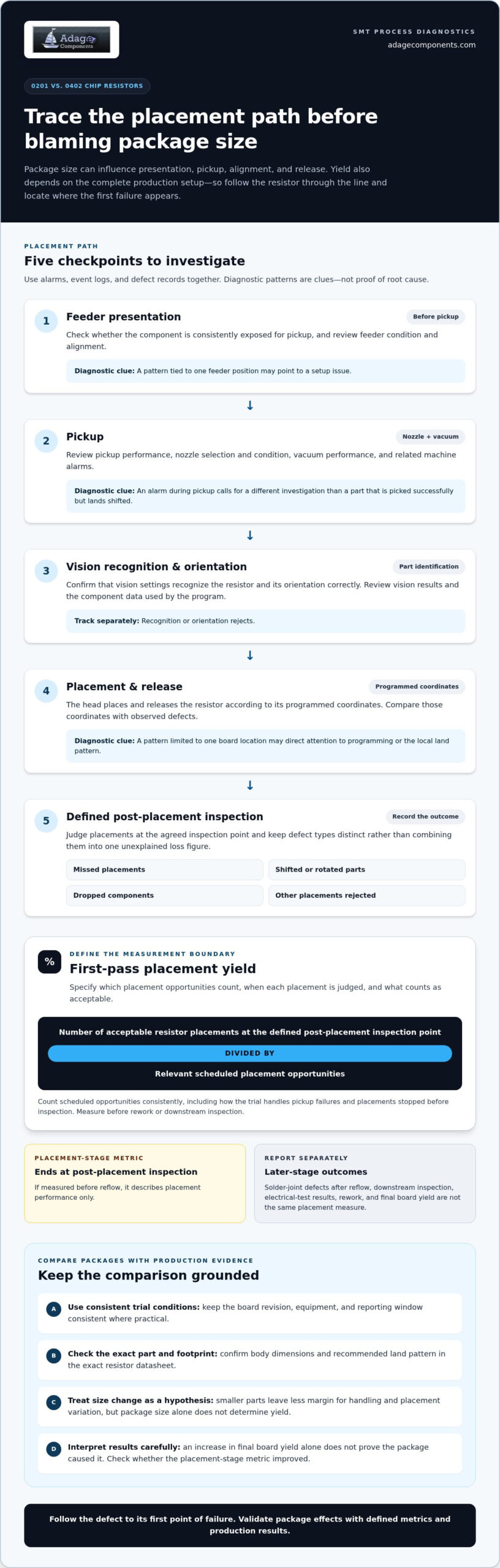
Start by defining the measurement boundary. Specify which placement opportunities are eligible, when each placement is judged, and what counts as acceptable. If the metric ends at post-placement inspection before reflow, it describes placement performance only. It doesn’t capture solder-joint quality, downstream inspection, electrical-test results, or final board yield after rework.
What do the 0201 and 0402 package codes mean?
0201 and 0402 are imperial package designations. Metric package codes use a different naming convention, so don’t infer a metric designation from the imperial code alone. Package codes describe a size class, not a complete resistor specification. Confirm the actual body dimensions and recommended land pattern in the datasheet for the exact manufacturer and part number. Resistance value, tolerance, resistor technology, and power rating are separate selection parameters.
This distinction matters when comparing parts. Two resistors with the same package code may have different specifications or physical details. For background on the broader assembly method, see Surface-mount technology (SMT). For a production decision, use the selected resistor’s datasheet and the board’s actual footprint data.
Which yield losses should the comparison measure?
Keep placement defects in distinct categories instead of combining them into one unexplained loss figure. Depending on the line’s inspection and event records, track missed placements, shifted or rotated parts, dropped components, and other placements rejected at the defined inspection point. Record the denominator too: count scheduled placement opportunities consistently, including how the trial handles pickup failures and placements stopped before inspection.
First-pass placement yield is the number of acceptable resistor placements at the defined post-placement inspection point divided by the relevant scheduled placement opportunities, before rework or downstream inspection.
This boundary keeps placement results separate from solder-joint defects such as opens, bridges, or tombstoning, which are assessed after reflow. Final board yield may also include downstream inspection, electrical testing, and rework. Report those outcomes separately. Otherwise, a package comparison can wrongly assign a later-stage failure to pick-and-place performance.
For a useful 0201 vs 0402 chip resistor pick and place yield loss comparison, align defect definitions and reporting boundaries before reviewing results. If line data shows improvement after a package change, check whether the placement-stage metric improved. An increase in final board yield alone doesn’t prove the package caused it.
How 0201 and 0402 Resistors Interact With the Pick-and-Place Process
A placement defect can begin before the machine head reaches the board. Follow the component through each stage, then use alarms and defect records to locate where the first failure appears. A smaller package may interact differently with a feeder, pickup setup, vision system, or placement program, but no single equipment setting applies universally to every 0201 or 0402 part.
Trace the placement sequence
Start with feeder presentation: is the part consistently exposed for pickup? Next, review pickup and vacuum performance, followed by the machine’s vision recognition and orientation check. The head places and releases the resistor according to its programmed coordinates. Finally, inspect the board at the defined post-placement point. An alarm during pickup calls for a different investigation than a part that is picked successfully but repeatedly lands shifted.
Review equipment alarms, event logs, and defect records together. Check whether events cluster around a particular machine, feeder position, component reference designator, or production lot. A pattern tied to one feeder position may point to a setup issue; a pattern limited to one board location may direct attention to programming or the local land pattern. Treat these as diagnostic clues, not proof of root cause.
Which placement variables can influence small-resistor defects?
Review feeder condition and alignment, pickup setup, nozzle selection, vacuum performance, and placement programming against the machine and component documentation. Confirm that vision settings recognize the part and its orientation correctly. Compare 0201 and 0402 defect records by reference designator, machine, feeder position, and lot. If a defect follows a feeder or machine rather than the package across the line, investigate that equipment path before attributing the loss to size.
- Pickup failures: Inspect feeder presentation, nozzle condition, and vacuum-related alarms.
- Recognition or orientation rejects: Review vision results and the component data used by the program.
- Repeated positional errors: Compare programmed placement coordinates with observed defects and board locations.
How do footprint and solder-paste conditions complicate the comparison?
A package change can also change the land pattern and the conditions around it. Verify the footprint against the resistor manufacturer’s recommendation and the PCB design data. Review board fabrication and pad geometry separately from the component itself. Then assess stencil apertures, paste deposition, and component spacing as distinct variables. These factors can affect placement observations and subsequent soldering outcomes, so log them rather than treating every defect as a machine-placement failure.
Package size alone cannot diagnose a placement-yield problem because equipment setup, board geometry, fabrication, solder-paste deposition, and program data can produce similar defect patterns. For a sound comparison, identify which variables changed and when, then match each observed defect to its earliest recorded process stage. The phrase 0201 vs 0402 chip resistor pick and place yield loss describes a comparison to investigate, not a diagnosis or predicted result.
Component documentation is one input to that investigation. Adage Components’ resistor and electronic component categories can help teams identify relevant parts for a specification review. Line data remains essential to process validation.
0201 Vs. 0402 Chip Resistors: A Production-Focused Comparison
Choosing between 0201 and 0402 means balancing board density against the demands of the actual assembly process. A 0402 may be worth evaluating where layout permits, but a larger package doesn’t guarantee better yield. A 0201 can remain the right choice when space is constrained and production data supports its use under the intended build conditions.
| Decision factor | 0201 | 0402 | Evidence to review |
|---|---|---|---|
| Board-area demand | Uses less board area, subject to the selected part’s dimensions and land pattern. | Requires more board area than 0201; confirm available clearance in the layout. | PCB layout, spacing, routing, and the manufacturer’s recommended footprint. |
| Placement sensitivity | Smaller size may leave less margin for handling and placement variation. | Larger size may be less demanding in some setups, but line performance must be measured. | Defined placement defects, machine records, and results from the intended process. |
| Footprint implications | Uses a package-specific land pattern that must match the component and board design. | Typically requires a different land pattern; layout and PCB changes may be necessary. | Datasheet recommendations, PCB design data, and qualification requirements. |
| Decision evidence | Retain when design constraints and validated production results support it. | Evaluate when the layout can accommodate it and a trial can isolate the change. | Part datasheets, board constraints, and controlled production comparison. |
Package size does not define electrical performance. Confirm resistance value, tolerance, technology, and power rating against the datasheet for the exact resistor part. A package code alone isn’t enough to establish whether a component meets the circuit’s operating needs or qualification criteria. Any substitution also needs a footprint and board-design review.
When should an engineer retain 0201 resistors?
Keep 0201 where layout density is a documented design requirement and the selected resistor meets circuit and qualification needs. Retention is also reasonable when validated line data shows acceptable placement results for the intended board revision, equipment setup, and build conditions. That evidence supports a production decision; package size alone does not establish process capability.
When is a 0402 trial worth considering?
Consider a 0402 trial if recurring placement defects correlate with specific 0201 reference designators. First confirm that the board can accommodate the larger footprint without compromising pad design, routing, spacing, or circuit requirements. Measure the result under documented conditions instead of presuming a yield gain.
The practical decision in a 0201 vs 0402 chip resistor pick and place yield loss review is not simply “smaller or larger.” It is whether the package fits the board, satisfies the exact part requirements, and performs acceptably in production. Preserve 0201 when the design requires it and the line demonstrates capability; trial 0402 when the layout allows and production evidence justifies evaluation.
Testing if Moving From 0201 to 0402 Reduces Yield Loss
A package change should earn approval through a controlled comparison, not a promising result from a single build. Begin with a baseline using the same yield definition, board revision, equipment, and reporting window. Record the number of eligible placement opportunities alongside accepted placements, so the result can be interpreted consistently rather than as a raw defect count.
How should the comparison trial be controlled?
Set the trial scope and acceptance criteria with the responsible engineering and manufacturing teams before production begins. Keep build conditions as comparable as practical, and record the board revision, resistor part and lot, machine, feeder position, placement program, and inspection method. If a 0402 requires a new footprint, PCB revision, or program adjustment, document each change and treat it as a potential contributor to the result.
Change only the package under study where practical. Some differences are unavoidable: a 0402 may require a different land pattern, and a substitute resistor may have a different part number or component lot. Capture those details rather than describing the comparison as package-only. If equipment, paste process, board revision, or inspection criteria also change, the trial can show that performance changed, but it can’t cleanly attribute the change to package size.
- Before the build: Record the baseline metric, trial scope, board and program identifiers, component details, and agreed acceptance criteria.
- During the build: Log production conditions, machine or feeder changes, alarms, and placement defects by category.
- After the build: Separate first-pass placement, rework, and final acceptance results, then note any deviations from the planned conditions.
What evidence supports a package-change decision?
Review each measure independently. Compare first-pass placement results and defect categories, then assess rework and final board acceptance separately. A reduction in one placement defect doesn’t automatically establish an improvement in final yield. Check whether the observed direction holds across relevant builds and conditions before revising released documentation or qualifying the new part for production.
Before approval, engineering and quality teams should assess electrical requirements against the exact resistor datasheet, along with footprint and routing constraints, assembly process impacts, and applicable qualification requirements. Component specifications and samples can support part comparison, but production data must establish process performance. For broader sourcing and qualification considerations, see The Strategic Guide to Sourcing Passive Electronic Components for OEMs.
The 0201 vs 0402 chip resistor pick and place yield loss decision is strongest when the trial distinguishes correlation from cause. A repeatable result under documented conditions gives the team a defensible basis for retaining 0201 or qualifying a 0402 alternative.
Adage Components provides authentic resistor options for part comparison and qualification. Review Adage Components’ resistor offerings.
Sourcing 0201 and 0402 Chip Resistors With Yield Control in Mind
We support OEMs with authentic electronic components sourced through direct verified procurement channels. Our component sourcing can support your qualification and procurement priorities, while production-line validation establishes process performance. With 30+ Years Experience, we help customers compare component options and pursue manufacturer pricing and cost-effective alternatives.
How do component records support a controlled comparison?
Keep manufacturer part numbers, datasheets, samples, and approved alternatives linked to the trial record. Two parts with the same package code aren’t automatically equivalent. Compare each exact resistor’s electrical specifications, technology, package details, and application requirements, then record differences that may affect design approval or qualification.
We work with vetted manufacturers and partner suppliers. Our pin-for-pin replacement support includes a spec sheet and/or samples for engineering review. Your team can assess the candidate part against its application and qualification criteria using those records.
Submit component requirements through the BOM submission form to align part details with your sourcing review. We also support international logistics and global stocking programs to help OEMs manage component supply and procurement planning.
How can verified sourcing support procurement continuity?
Verified sourcing helps maintain a clear link between the component evaluated and the part procured. We use direct verified procurement channels and conduct in-person manufacturing audits worldwide. Our diode OEM partner’s stated certifications include ISO 9001, IATF 16949, ISO 14001, and QC080000. These sourcing controls support component integrity; your production trial remains the evidence for placement performance.
Pin-for-pin replacement is an evaluation route, not automatic approval. Review the exact datasheet, sample, footprint, and qualification requirements before authorizing a substitution. Our international logistics program supports component sourcing for OEMs, with options aligned to your requirements. For a broader procurement perspective, see Electronic Component Distributors: A Strategic Sourcing Guide for 2026.
Start your component review with the Adage Components resistor and component line card.
Make the Next Package Decision Evidence-Led
Use your trial results to guide the next design and procurement review. If 0201 meets board-density needs and performs reliably under the intended build conditions, retain it. If recurring defects justify further evaluation and the layout permits a larger footprint, qualify 0402 through a controlled comparison. Keep engineering, manufacturing, and procurement aligned on the exact part and the evidence behind the decision.
For the 0201 vs 0402 chip resistor pick and place yield loss question, match component options to your design requirements, then validate any change on the production line. Adage Components brings 30+ Years Experience in electronic component sourcing, with support for component evaluation.
Review the Adage Components line card to explore resistor categories for your next qualification review. Align your component requirements with authentic options and submit your BOM for a sourcing review.
Frequently Asked Questions
Does switching from 0201 to 0402 always improve pick-and-place yield?
No. A 0402 may be easier for a particular line to handle, but a package change can’t correct unrelated causes such as a feeder issue or an inaccurate placement program. For 0201 vs 0402 chip resistor pick and place yield loss, compare builds using the same inspection rules and report placement results separately from rework and final board acceptance. If the trial also changes the board or machine setup, record those changes before drawing conclusions.
Why can 0201 resistors be more challenging to place?
The smaller body can leave less tolerance for variation during pickup, recognition, and placement, but it doesn’t guarantee poor results. Consider the pattern: if failures appear after a feeder changeover, investigate that event rather than treating all 0201 positions as equally problematic. If defects recur at one reference designator across builds, compare its board location, component data, and machine records. This helps distinguish a local issue from a package-wide trend.
Can a 0402 resistor use the same PCB footprint as a 0201 resistor?
Don’t assume the footprints are interchangeable. A package change can require updates to the PCB library, design files, assembly documentation, and revision controls. Review clearances to nearby components and whether the larger land pattern affects routing or available placement area. Confirm the exact part’s dimensions and recommended land pattern in its manufacturer datasheet, then route the proposed change through the design review process before release.
How should engineers measure pick-and-place yield loss for 0201 and 0402 parts?
Define the inspection point and counting rules before collecting trial results, then apply them consistently to both packages. Preserve results by reference designator as well as by build, so a strong overall result doesn’t hide a recurring problem at one board location. Keep placement rejects distinct from rework and downstream test failures. A concise trial record should let another engineer reproduce the calculation from the source production data.
What should be checked before changing a resistor from 0201 to 0402?
Confirm the circuit’s operating requirements and the candidate part’s documented characteristics, then check board space, layout effects, and qualification needs. Before release, align the updated component record with the bill of materials, approved-parts list, and relevant design documentation. This avoids a mismatch between the part engineering evaluated and the part procurement or production later references. Keep the trial outcome attached to the approval record.
Can an 0201 or 0402 resistor package determine electrical performance by itself?
No. The package designation indicates a physical size convention, not the complete electrical behavior of a resistor. Two parts in the same package can differ in resistor technology or other application-relevant ratings. For example, matching resistance and tolerance alone may not establish suitability if the circuit has additional power or environmental requirements. Use the exact manufacturer datasheets and evaluate each candidate against the design’s electrical and qualification criteria.
Disclaimer
Cross-referenced components needs to be confirmed by the client with either spec. sheet or samples or both.
Please note, we use AI to help us, information is verified to be correct but we can not guarantee 100% accuracy.