

Could a RoHS-compliant chip still be damaged during reflow? Yes. RoHS lead-free solder reflow peak temperature limits for chip components aren’t set by RoHS itself. The directive restricts certain hazardous substances; it doesn’t establish a universal oven temperature. A profile that works for one assembly could exceed another component’s thermal rating.
It’s understandable to look for one safe peak temperature, especially because lead-free soldering brings thermal demands that must be managed. The applicable limit depends on the component’s rating and assembly conditions. This article explains how to identify the relevant component limit, interpret J-STD-020F reflow classifications, and qualify a profile against datasheets, board design, and solder-paste requirements rather than treating a classification temperature as an oven setpoint.
Reliable qualification also depends on traceable parts and current documentation. Adage Components supplies electronic components to OEMs and EMS providers, with technical support and quality assurance services that help connect component sourcing with approved-part review.
Key Takeaways
- RoHS restricts specified substances; it doesn’t set a universal reflow peak temperature for chip components.
- Understand how profile stages and actual component-body temperatures affect thermal exposure during lead-free reflow.
- Use datasheets, JEDEC classification conditions, and solder-alloy data for their distinct purposes when setting process limits.
- Apply a documented qualification workflow to compare measured temperatures and exposure times with each component’s applicable limits.
- Review the RoHS lead-free solder reflow peak temperature limits for chip components alongside traceable BOM records and current component documentation.
Does RoHS Set Lead-Free Reflow Peak Temperature Limits for Chip Components?
No. RoHS restricts specified hazardous substances; it doesn’t prescribe one universal peak temperature for lead-free reflow. A component’s RoHS status tells you about substance compliance, not how much heat it can withstand during assembly. The RoHS lead-free solder reflow peak temperature limits for chip components must be established from the applicable component documentation and a qualified process profile.
Keep three thermal considerations separate. The solder alloy’s melting behavior informs the temperatures needed for soldering. The component’s capability sets its documented thermal boundaries. The assembly process window describes the temperatures and exposure times needed to form reliable joints without exceeding component limits. Reflow soldering involves stages such as preheating, soaking, reflow, and cooling; the Reflow soldering overview provides useful context for how these stages fit together.
For a related look at post-soldering PCB handling, watch this video:
What RoHS Covers, and What It Does Not
RoHS is a substance-restriction framework, not a soldering recipe. Moving to lead-free solder can change an assembly’s thermal demands, but lead-free compliance alone doesn’t establish a component’s thermal tolerance or approve a particular oven profile. Regulatory compliance addresses restricted substances; process qualification verifies that the assembly’s measured thermal exposure stays within component and process requirements.
Why Chip-Component Temperature Limits Are Component-Specific
Thermal limits can vary with package construction, size, and component family. A chip resistor and a multilayer ceramic capacitor may respond differently to the same board profile because their materials and internal structures differ. Ratings can also vary among parts within one family. Don’t apply a limit from a similar-looking part or treat a general package classification as approval for the exact component.
Use the current datasheet and applicable qualification documentation for the precise manufacturer part number. Check the stated peak temperature, exposure duration, and any conditions or restrictions, then verify the assembly profile against those requirements and applicable standards. If a datasheet revision or approved part changes, reassess the qualification record before relying on the existing profile.
How Lead-Free Reflow Profiles Expose Chip Components to Heat
A reflow profile describes an assembly’s thermal history, not just the temperature displayed on the oven. Its stages control how solder paste activates, melts, and cools, while each component experiences heat according to its location and construction. To qualify the RoHS lead-free solder reflow peak temperature limits for chip components, assess measured temperatures and exposure times on a representative assembly instead of relying on oven settings alone.
Lead-free alloys don’t all behave alike. Their liquidus temperatures and supplier-recommended processing conditions can differ, so use the selected alloy’s technical documentation when setting the process window. The European Commission’s RoHS Directive is a regulatory reference; solder-alloy supplier documentation informs the alloy-specific process requirements.
What Peak Temperature and Time Above Liquidus Mean
Peak temperature is the maximum temperature recorded at a measurement point during the reflow cycle. It isn’t necessarily the oven’s setpoint. Time above liquidus (TAL) is the time the solder is above the liquidus temperature of the selected alloy. Both values depend on where and how temperature is measured, so profile reports should identify sensor locations and use the alloy supplier’s liquidus and process recommendations.
The profile typically moves through these stages:
- Preheat: The assembly warms at a controlled rate.
- Soak: Temperatures stabilize across the board and solder paste activates according to its requirements.
- Reflow: The solder passes above liquidus; the cycle reaches its measured peak.
- Cooling: The assembly cools after reflow, completing the thermal cycle.
Why Board Location and Thermal Mass Matter
A board’s layout creates local differences in heat response. Copper distribution, component density, board thickness, and nearby thermal mass can make one area heat or cool differently from another. A sensor near the board center may not capture exposure at a component near an edge, beside a large thermal mass, or in a densely populated region.
Oven setpoint is the machine’s control target. Board temperature records the assembly’s response, while a thermocouple attached to a component body measures that component’s local exposure. These readings aren’t interchangeable. Profile representative hot and cold locations with appropriately placed thermocouples, then compare peak and time-above-liquidus readings with the applicable component and solder-paste documentation. Recheck after meaningful changes to the board, loading, alloy, or process conditions.
For part selection and BOM review, Adage Components’ electronic components line card provides a reference to its component offerings.
Datasheet Ratings, JEDEC Classification, and Solder-Alloy Data: What Sets the Limit?
No single reference answers every reflow question. A component datasheet defines part-specific conditions, JEDEC classification describes a package’s moisture/reflow sensitivity classification, and solder-material documentation guides processing of the selected alloy. Use each source for its intended purpose, then compare them during profile qualification. This distinction is central to establishing the RoHS lead-free solder reflow peak temperature limits for chip components.
| Document source | What it defines | How engineers should use it |
|---|---|---|
| Exact component manufacturer’s datasheet | Part-specific soldering or reflow conditions, which may include peak temperature, exposure time, cycle count, or package restrictions. | Use as the primary component-specific reference and check the exact part number and current revision. |
| JEDEC J-STD-020F | Moisture/reflow sensitivity classification conditions for nonhermetic surface-mount devices. | Use to understand the component’s classification, not as a standalone production-profile recipe. |
| Solder-alloy supplier documentation | Alloy properties, including liquidus information and supplier-recommended processing guidance. | Use to set alloy-related process parameters, then verify compatibility with every component and the assembly. |
How to Read Component Datasheet Reflow Ratings
Find the soldering or reflow section for the exact manufacturer part number. Check whether the stated conditions specify a peak, time at temperature, permitted reflow cycles, or package-specific restrictions. Confirm how temperature is defined and measured where the datasheet explains it, and note the document revision used for qualification. The current datasheet for the exact part is the component-specific reference for its reflow limits.
How to Use JEDEC J-STD-020 and Solder-Alloy Information
J-STD-020F, published in 2022, addresses moisture/reflow sensitivity classification. Its classification temperature is tied to package characteristics and test conditions; the series includes classification temperatures such as 245°C, 250°C, or 260°C. These values aren’t automatically recommended production targets. A classification test condition and a board-level profile serve different purposes.
For production, use the datasheet’s part-specific conditions alongside measured assembly temperatures and exposure times. Check the current applicable standard revision and confirm its scope for the component under review. Then consult current solder-material documentation for the selected alloy’s liquidus and process guidance. Alloy data alone cannot prove component compatibility, and a classification rating alone doesn’t qualify an assembly profile. The qualified process must satisfy the relevant requirements together.
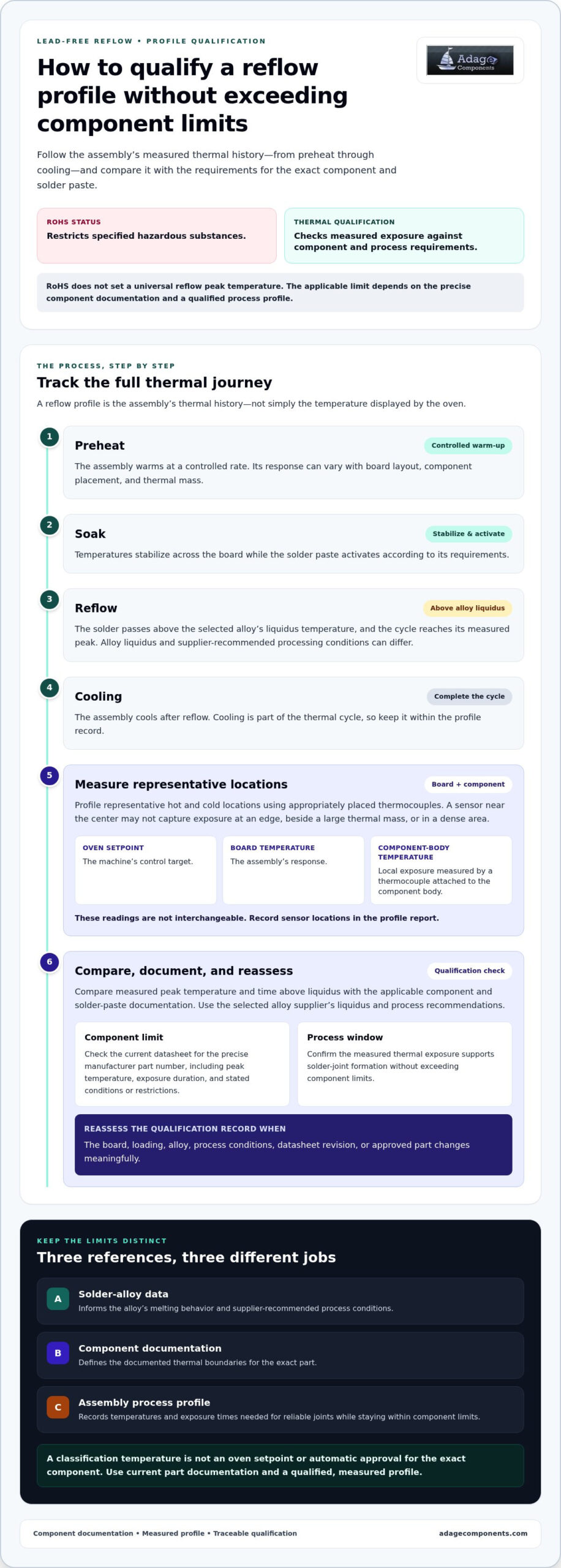
How to Qualify a Lead-Free Reflow Profile Without Exceeding Component Limits
A defensible reflow profile connects approved component documentation to measured assembly temperatures. For the RoHS lead-free solder reflow peak temperature limits for chip components, don’t approve a process based on an oven recipe or a single peak reading. Review each part’s applicable limits, check representative board locations, and retain the evidence behind the production decision.
A Practical Component-to-Profile Review Sequence
Use a controlled sequence so component changes and process assumptions don’t get lost between engineering, quality, and procurement:
- Identify the parts. Record exact manufacturer part numbers, package details, approved alternates, and the current datasheet and qualification records for each component.
- Define the proposed process. Document the solder alloy, profile settings, expected reflow cycles, and assembly conditions that could affect thermal exposure.
- Measure representative assemblies. Use thermocouples at selected component locations, including expected hot and cold areas. Capture peak temperature and time above liquidus where applicable.
- Compare part by part. Map each measured temperature and exposure time against the relevant manufacturer limits and conditions. Include any restrictions on cycle count or package use.
- Review variation and repeatability. Consider board-layout or loading variation and determine whether the profile remains within documented limits across representative production conditions.
- Document disposition and validate production. Resolve conflicts through engineering review before approval. Record the accepted criteria, profile evidence, and production validation results.
Acceptance criteria must come from product requirements and verified manufacturer documentation. If an alternate component, board revision, solder alloy, or process condition changes, assess whether the existing qualification still applies before continuing production.
Thermocouple Placement and Profile Evidence
Place thermocouples at representative locations rather than assuming one board measurement describes the entire assembly. Include locations expected to heat fastest and slowest, and measure near components whose documented limits are most restrictive. Record sensor placement with the profile so results can be interpreted and repeated. A board-level sensor can help characterize the assembly, but it may not reflect every component’s local exposure.
Measured component-area profiles provide stronger qualification evidence than oven setpoints because they record the thermal exposure the assembly actually experiences. Review peak and exposure time together, then retain the profile and component-document references in the qualification record.
Use Adage Components’ electronic components line card to review component categories relevant to approved-part selection and BOM planning.
Choose Traceable Chip Components for a Qualified Reflow Process
A qualified profile is only useful if the parts entering production match the parts whose limits were reviewed. Component traceability links the manufacturer part number, technical documentation, and approved BOM record to the engineering decision. That control helps prevent an unreviewed alternate or documentation revision from undermining the qualification basis.
What Procurement Teams Should Preserve in the BOM Record
Keep the sourcing record aligned with engineering’s approved-part data. For each chip resistor, ceramic capacitor, or other passive component, preserve:
- Exact manufacturer part number and approved alternatives, including any conditions on substitution.
- Revision-controlled datasheets and relevant qualification documentation used to establish thermal limits.
- Applicable assembly constraints and the profile evidence used to qualify the part.
- Supplier and lot traceability records needed to connect purchased material to the approved BOM.
These records give procurement and engineering a shared reference when reviewing alternates, BOM changes, or production requirements. Adage Components supplies passive components to OEMs and EMS providers and provides technical support and quality assurance services to support component review and sourcing.
Align Component Sourcing with Production Requirements
Document the application and approved-part requirements in the BOM so sourcing decisions remain connected to the qualified assembly process. Adage Components supplies electronic components, including thick film chip resistors, and provides technical support, manufacturing audits, and quality assurance services. Its supply chain and logistics services include global stocking programs and international logistics coordination, which can help businesses manage material costs and lead times.
For OEMs and EMS providers, Adage Components offers cost-effective alternatives and drop-in replacements for standard industry parts. Supply planning is more effective when the BOM identifies the exact approved part, acceptable alternates, required documentation, and any assembly constraints.
Review the passive component line card to identify relevant categories for your BOM. For sourcing support tied to your approved part requirements, submit your project BOM.
Build a Reflow Process You Can Defend
Reliable lead-free assembly depends on matching the approved component to the qualified process. RoHS restricts specified substances, but it doesn’t set a universal peak temperature. The RoHS lead-free solder reflow peak temperature limits for chip components must be established from current manufacturer documentation and verified against measured temperatures and exposure times on representative assemblies.
Keep the evidence connected: exact part numbers, revision-controlled datasheets, applicable qualification records, and approved BOM entries. Treat JEDEC classification conditions and solder-alloy guidance as distinct inputs, not substitutes for component-specific limits or production profile validation. Reassess the qualification when a part or relevant process condition changes.
Adage Components supplies electronic components for OEMs and EMS providers, including thick film chip resistors, and provides technical support and quality assurance services. We help connect component sourcing with documented application requirements and approved BOM records.
Review the electronic component line card and submit your project BOM to align component sourcing with your approved requirements.
Frequently Asked Questions
Does RoHS specify a maximum reflow temperature for chip components?
No. RoHS restricts specified hazardous substances in applicable electrical and electronic equipment; it doesn’t set a universal soldering peak for chip components. The RoHS lead-free solder reflow peak temperature limits for chip components come from the exact part’s current manufacturer datasheet and applicable qualification documents. Compare those conditions with measured temperatures on a representative populated board and the selected solder alloy’s current process guidance before approving production.
What peak temperature is safe for lead-free reflow soldering?
There’s no single peak that’s safe for every lead-free assembly or chip component. The allowable profile depends on the exact component and package, selected solder alloy, exposure duration, and manufacturer instructions. Treat generalized temperature values as screening references, not approval criteria. Before production, compare the complete profile, including measured peak and exposure time, with current part documentation using a representative populated board and a documented engineering review.
Is a JEDEC peak temperature the same as a component’s recommended reflow temperature?
Not necessarily. A package classification condition defined by a JEDEC method serves a different purpose from a production recommendation for a specific component. Check the standard’s scope and applicable revision, then consult the manufacturer’s datasheet for that part’s reflow conditions. Don’t copy a classification temperature into a production recipe without confirming its meaning, applicability, and relationship to measured board conditions.
Can chip resistors withstand multiple lead-free reflow cycles?
They may, but permitted cycle counts and conditions depend on the exact resistor series, construction, package, and manufacturer documentation. Don’t assume a limit for one chip-resistor family applies to another. Check the current datasheet and assembly guidance for cycle count, peak exposure, and restrictions. If production includes repeat reflow, include the full sequence in engineering qualification and compare the cumulative process conditions with the applicable requirements.
How do I verify the actual peak temperature experienced by a chip component?
Profile a representative populated assembly with thermocouples placed at locations that capture relevant thermal extremes. Record temperatures near component locations through the full reflow cycle, including peak and time above liquidus where applicable. Oven settings alone don’t establish each component’s temperature. Review sensor placement, board variation, and process repeatability, then compare the measured results with the documented conditions for each component.
Does lead-free solder always require a higher reflow peak than tin-lead solder?
No blanket rule applies to every process. The required window depends on the selected solder alloy and assembly materials, while each component has its own thermal constraints. Compare current alloy technical data with component datasheets and measured board profiles. Avoid assuming that all lead-free alloys behave alike or using a general lead-free-versus-tin-lead comparison to approve a production recipe.
Disclaimer
Cross-referenced components needs to be confirmed by the client with either spec. sheet or samples or both.
Please note, we use AI to help us, information is verified to be correct but we can not guarantee 100% accuracy.